|
<< Click to Display Table of Contents >> How is the Output Pin Used in the Event Vector Table? |
  
|
|
<< Click to Display Table of Contents >> How is the Output Pin Used in the Event Vector Table? |
|
Click here to download this example
The default is for entry to be on the input pin state. Consider the following code snippet.
else if ( IsMatchAEvent() && pin==0 )
{
ThreadLo:
...
}
else if ( IsMatchAEvent() && pin==1 )
{
ThreadHi:
...
In the above code, if there is a MatchA and the pin is low then ThreadLo executes. Otherwise, if there is a MatchA and the pin is high, then ThreadHi executes.
But which pin state is used, the input pin state or the output pin state? The default is the input pin state. For all but a few of the earliest (~2005 era) microcontrollers, this can be overridden and the output pin state can be used. The remainder of this tutorial covers which eTPU register to modify to use the output pin state, how to modify this register in the eTPU Simulator, and how to view the selection in the simulator.
A small number of early versions of the eTPU do not support entry on the OUTPUT pin state, see below for the list. For all other microcontrollers, this feature is supported. This is the list of microcontrollers that do not support using the OUTPUT pin state in the 'Event Vector Table'. (All other microcontrollers support this feature.)
•MPC5554-B
•MCF5232-0
•MCF5233-0
•MCF5234-0
•MCF5235-0
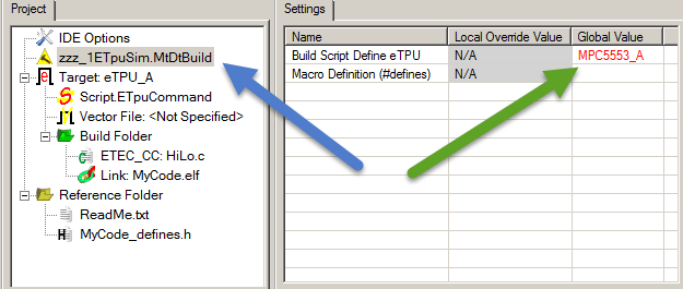
Not all microcontrollers support using the output pin (in lieu of the default which is the input pin) as a conditional to the event vector table. So a microcontroller must be simulated that supports this feature as follows. The eTPU Simulator supports setting the microcontroller type in two ways. It can either be specified on the command line when the simulator is launched or from the Mtdt Build Script, as shown below. To specify this setting, select the Mtdt build script node in the project (see the blue arrow, below) and specify the desired microcontroller type to simulator in the settings window (see the green arrow, below.)
To support the microcontroller version from the command line, search for "Command Line Parameters" in the online help.
When the microcontroller type is specified in BOTH the command line AND the settings window, then the command line option takes precedence.
The eTPU Register that supports this is the Channel x Configuration Register (CxCR) field Entry Table Pin Direction (ETPD) field. This field must be set to a one for the the output pin state to be used as the entry condition. So CxCr.ETPD must be set.
In the simulator, the script for specifying the CxCr.ETPD value is as follows.
write_chan_entry_pin_direction(ChanNum, Val);
A Val of '0' (which is the default) specifies entry on input pin state, a value of '1' specifies output pin state. The following example (taken from the user manual) shows configuring UART channels for output and input.
#define ETPD_PIN_DIRECTION_INPUT 0
#define ETPD_PIN_DIRECTION_OUTPUT 1
write_chan_entry_pin_direction(UART1_CHAN, ETPD_PIN_DIRECTION_INPUT);
write_chan_entry_pin_direction(UART2_CHAN, ETPD_PIN_DIRECTION_OUTPUT);
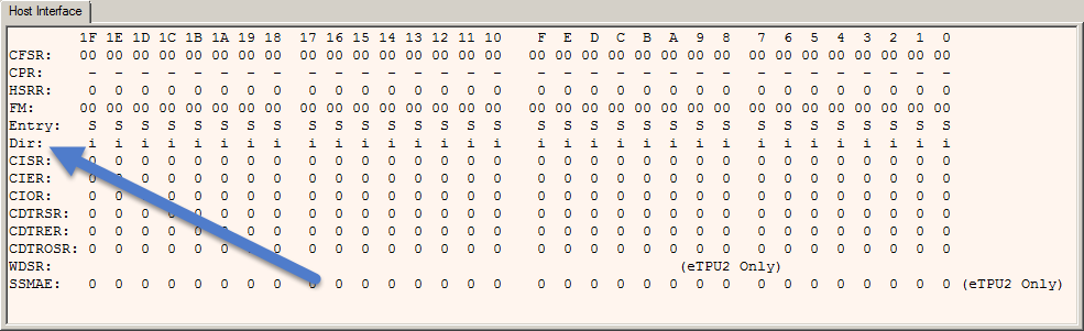
The eTPU Simulator window that displays this CxCr.ETPD value is the Host Interface Registers Window. To view this window, select the from the View menu, select the Host I/F Window sub-menu and the following window appears. The ETPD value for each channel is shown in the row labeled "Dir". As shown below, channel 4 is the only channel that has been configured to Output (Output is designated with the 'O', inputs with 'i'.)