|
<< Click to Display Table of Contents >> Synchronously Toggle Multiple Output Pins |
  
|
|
<< Click to Display Table of Contents >> Synchronously Toggle Multiple Output Pins |
|
Click here to download this example
It is possible to have one channel control the output pins on other channels. This overview and example assume that a relatively quick response time is required such that the output pins need to change within a micro-second or so. The approaches covered here all write the 'chan' register to the number corresponding to the output channel whose pin will be changed. Once the channel register is changed, either a match can be used to modify the pin value, or the pin value can be changed directly. The advantage of using a match is that multiple output pins can be transitioned at the exact same time by using the same match value for all the channels. The advantage of controlling the output pin directly is that it is quicker and requires less code.
Another approach not covered here would be to issue links to the multiple output channels. The output channels would respond to the link events by executing link event handling threads in which each channel would control its own output channel. Since it takes one thread for each output channel, this approach, depending on what else is running in the system and the resulting Worst Case Latency (WCL), could take tens of microsecond for all the output pins to transition. This might be too much delay, especially in (say) the MUX example presented here.
Some of the key concepts covered here are saving and restoring the channel number of the controlling channel in a local variable, storing a common 'match' time in a local variable, and accessing channel variables in the original channel. There are many 'tricks' that can be played to make the above easier such as setting the CPBA registers of the output channel equal to that of the controlling channel (see 'Approach #2') or bypassing the need to store the output channel numbers in a variable by locating the output channels in contiguous channel numbers (approach #4.)
The following snippets sets a time at which the output pin will toggle. It must be sufficiently far in the future such that the thread has time to arm the channel hardware for all the channels that will synchronously toggle. In this case the thread takes 0.72 micro-seconds to execute at 100 MHz so the match time is set for 1.00 microseconds in the future.
int toggleCount = tcr1 + 50;
The following code snippet shows how the very first output pin is armed to toggle using the match hardware.
//-------------------------------------------
// Set or clear the first channel's output pin
chan = (unsigned char) _firstChanNum;
if( (bitPattern & 1) != 0)
{
OnMatchAPinHigh();
}
else
{
OnMatchAPinLow();
}
SingleMatchSingleTransition();
ActionUnitA( MatchTCR1, CaptureTCR1, GreaterEqual );
ertA = toggleCount;
ClearMatchAEvent();
WriteErtAToMatchAAndEnable();
Subsequent output pins are slightly different from the above in that the original channel must be restored in order to access its channel variables. This is done by the chan = (unsigned char) savedChan; line of code, below.
//-------------------------------
// Go back to original channel
// before reading the channel variable
chan = (unsigned char) savedChan;
// Set or clear the second channel's output pin
chan = (unsigned char) _secondChanNum;
bitPattern = bitPattern >> 1;
if( (bitPattern & 1) != 0)
{
OnMatchAPinHigh();
}
else
{
OnMatchAPinLow();
}
SingleMatchSingleTransition();
ActionUnitA( MatchTCR1, CaptureTCR1, GreaterEqual );
ertA = toggleCount;
ClearMatchAEvent();
WriteErtAToMatchAAndEnable();
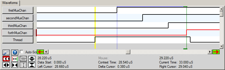
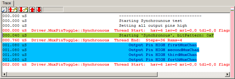
In the trace window below the thread is shown to start at simulation time 0.000 micro-seconds. The channel on which the thread starts has been assigned the name 'Driver' and the eTPU function is named 'MuxPinToggle', and the the thread is named 'Synchronous. This particular thread has been assigned to handle the 'HSR 6' event which (in this case) is a request from the host CPU to toggle four output pins in a Multiplexer (MUX) application. The thread ends at time 0.760 micro-seconds, but the output pins don't toggle until after the thread ends ... at 1.08 micro-seconds. Most importantly, all four output pins toggle synchronously at 1.080 microseconds. The comments in the trace window such as "Starting 'Synchronous', bitPattern=0xF have been injected into the trace window in the code using the '// @ASH@print_to_trace("Starting 'Synchronous', bitPattern: 0x%X",_bitPattern );' syntax and also in the script commands file using the 'print_to_trace' script command.
In the waveform below the 'Delta Cursor' shows the thread length to be 0.720 microseconds. The thread ends at time 0.760 micro-seconds shown in 'Right Cursor'. Note that the four output pins synchronously toggle from low to high AFTER the thread ends at 1.080 micro-seconds shown in 'Context Time.'
Perhaps the best alternative approach would be (instead) to locate the channels on sequential channels. For example, use channels 20, 21, 22, and 23. This has two advantages. First, the original channel number need not be stored in variable 'savedChan'. Instead, when to switch to the next output pin's channel simply increment the channel register by 'chan = chan + 1'. The other advantage is that the channel numbers of the output pins need not be stored in their own channel numbers. So variables '_secondChanNum, _thirdChanNum, _fourthChanNum' and possibly also '_firstChanNum' might not be needed.
Another really good alternate approach is to have all the output channels have their channel variables at the same address. The advantage to this is that the original channel need not be restored when reading variables '_secondChanNum, _thirdChanNum, _fourthChanNum'. To have the channels share channel variables their Channel Parameter Base Address Registers (CPBA) must be set to the same value.
Alternative Approach #3, 'Global Variables'
The advantages of the original approach and the above two alternative approaches is that they support multiple groups of synchronously-toggling output pins. However, if the system would have just one group of output pins that need to synchronously toggle, the instead of storing the output channel numbers in channel variables, the output pin numbers could be stored in global variables. This would also obviate the need storage and restoration of the original channel number in variable 'savedChan'.
In this approach the output pin is set or cleared directly using either 'SetPinHigh' 'SetPinLow' instructions as shown below. Advantages of this approach are that it takes less code and executes faster. Also, due to the shorter thread, the pins toggle more quickly. The disadvantage is that the output pins don't actually toggle synchronously but instead take a few hundred nano seconds from the first to last output pins to toggle (0.38 us in the example code.) So this solution would be termed 'Sequential' or 'Near Synchronous' rather than 'Synchronous.'
//-------------------------------------------
// Set or clear the third channel's output pin
chan = (unsigned char) savedChan;
chan = (unsigned char) _thirdChanNum;
bitPattern = bitPattern >> 1;
if( (bitPattern & 1) != 0)
SetPinHigh();
else
SetPinLow();
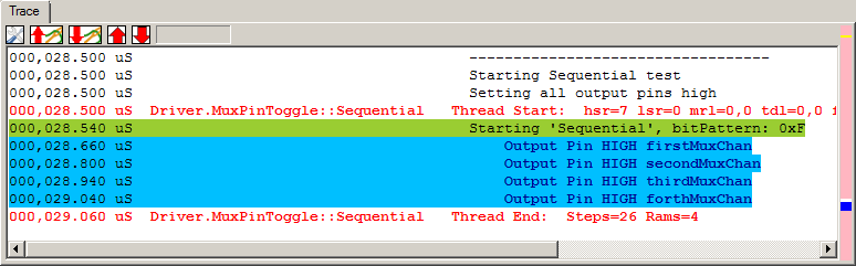
In this 'Sequential' approach the test is initiated with an HSR 7 event which causes the thread start at time 28.500 seen in the trace window snapshot, below. Unlike the true 'Synchronous' approach, this solution is 'Nearly Synchronous' in that there is a slight delay between pin toggles which occur at 28.540, 28.660, 28.940 and 29.400 microseconds, respectively. Since the output pins are being controlled directly within the thread by the 'SetPinHigh' instruction, the thread actually ends after ALL The output pins have toggled at 29.060 micro-seconds.
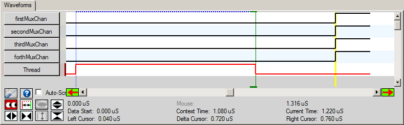
This same information can be viewed graphically in the waveform window, below. Note that this thread length is 0.520 micro-seconds long which is shorter than the true-synchronous's thread length of 0.720 micro-seconds (all at the pedestrian clock speed of 100 MhZ ... so a Cobra 55 would be almost 3X faster.) Also interestingly, the time from the HSR being issued by the host CPU to the pins actually changing is 0.500 micro-seconds so about half of the true synchronous approach. Of course both approaches would incur the Worst Case Latency which is shown as 0 in this simple example but in real world could be in the several micro-seconds range depending on the specifics of the system.