|
<< Click to Display Table of Contents >> How to Drive Input Pins with Output Pins |
  
|
|
<< Click to Display Table of Contents >> How to Drive Input Pins with Output Pins |
|
How can an output pin drive one or more input pins?
Say you have a bidirectional serial communications line in which you would like to both drive the line?
For a detailed discussion on this topic, in the help manual, go to the sections on, "EXTERNAL LOGIC SIMULATION" and "eTPU/TPU External Logic Commands." The following is pulled directly from the user manual.
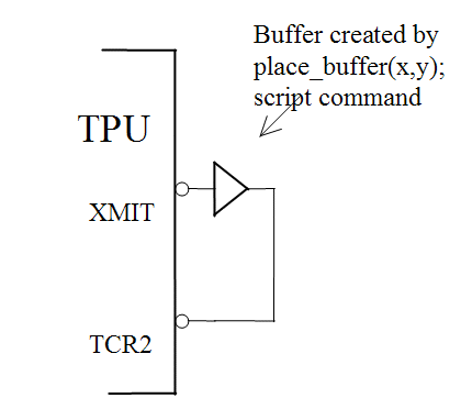
In the following example a TPU channel drives the TCR2 pin. The buffer is instantiated from within a script commands file using the place_buffer(X,Y) script command. The buffer's input is connected to the TPU channel's pin and the buffer's output to the TCR2 pin. The X variable is set to five to make TPU channel five the buffer's input. The Y variable is set to 16 as this is the index that MtDt uses for the TCR2 pin.
place_buffer(5,16);
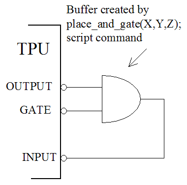
In the following multi-drop communications example TPU channel 5 is a communications channel output. TPU channel 7 is used as a gate to enable and disable the output. Channel 1 is the communications input. An idle line is low. An AND gate is instantiated using the place_and_gate(X,Y,Z) script command. The gate pin causes an idle (LOW) state on the input by going low. By going high the gate pin causes the state on the output channel to be driven unto the input channel.
place_and_gate(5,7,1);